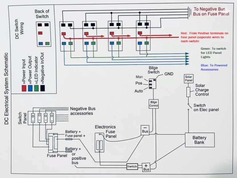
This boat seems typical of most old small sailboats. Electrical needs were simpler back in the 1970’s, and systems weren’t built for expansion and extra gadgets like they are in some modern boats. On this boat, the switch panel was small, and the cabinet behind it was also very small. A previous owner decided to use the space under the companionway step as a new area to run wires and mount equipment. He ran wires from the main 4-switch panel to terminal blocks under the step, and mounted two batteries in boxes in the lockers on each side of the step. In a small boat, this took up a lot of space in the cabin compartments, and the batteries were sitting at angles and loosely secured to the boat with nylon straps and plastic clamps.
With this setup, most of the wiring was within inches of the bilge water and the companionway opening. As a result, most of the connections were severely corroded–but surprisingly, almost everything worked. If you look at the picture of the old wiring above, you can see the bilge pump inches from an AC outlet.
The original switch panel and the solar charge controller.
The wiring and terminal blocks that were stuffed in the small space behind the switch panel.
A corroded connection for the water washdown pump that is in the cockpit locker.
Some of the old wiring runs across the top of the quarterberth.
The old rusty home-store circuit breaker box that was used for the shore power connection.
Making a plan
When rewiring a boat, it’s probably best to rip all the old stuff out and replace everything with new wires, switches, fuses, etc. However, I decided to keep some of the existing wiring and electronics to save time and money. The Sailstar and Bristol 26 were built with a liner on the cabin ceiling, which makes replacing those wires difficult. Luckily all of those wires were only for cabin lighting, so I decided to leave their old wiring in place and redo the connections I could reach.
The other, more recent wiring installed by previous owners was easily accessible since it wasn’t installed under any type of liner. I was able to reroute and organize it better, getting it out of places like the top of the quarterberth, the tops of lockers where it can get damaged, and the bilge areas.
Thinking about the layout
Some important things I learned about designing an electrical system for a small boat are:
recognizing the constraints of your space and choosing a system that makes the best use of the space you have.
Making sure you create a system that you can modify or expand in the future.
Making things accessible for maintenance and troubleshooting.
Coming up with a way to trace wires from the panels to the components.
I looked at using a circuit breaker panel, since they are readily available and simplify the wiring a bit. But, since the switch panel location was small and thin, I would have to either find a new space for the panels or modify the existing space to fit more wires and bus bars in it.
I decided to go with a simple switch panel in the original location, since it’s the most convenient spot for switches. The new switches didn’t have breakers built into them. The original ones had glass fuses. I needed some kind of wire protection, so I decided to mount two “Blue Sea” brand fuse blocks in the small storage locker in the middle of the dinette area on the port side of the boat. It’s a dry locker isolated from the bilge, and it’s shallow and offers limited storage—but it’s easy to access if you need to mess with or inspect the electrical system. And there is plenty of room to add an inverter or other small equipment in the future. I also liked that the fuse blocks allowed me to customize the fuse sizes according to the needs of the system. A lot of the switch panels I looked at had 15 amp circuit breakers, and were much more expensive than the setup I decided to use.
For the new switch panel, I decided to cut the area around the existing switch panel to provide better access to that area, and to maximize the space available for switches. I built a plywood cover and mounted two rows of 4 switches on it. I also mounted a switch that controlled the panel lights so you could shut them off at night and not have to sleep under the green glow of the panel lights. I also had room for a DC outlet and a USB outlet. On the back of the new cover, I mounted a bus bar to use for the lighting connections, since the old wiring terminated at the switch panel, and the cabin liner made it difficult to change that design.
Moving the wiring out from under the companionway step freed that area up, so I bought two AGM batteries and mounted them in place of the old wiring mess, using plywood strips and stainless brackets to keep them from moving around. It’s close to the boat’s centerline, and the AGM batteries are sealed, so they don’t need to be enclosed in boxes.
The new switch panel and DC outlets.
Working on the back of the switch panel and the new wiring. The bus bar for the cabin lights is mounted above the switches (in the bottom of the photo).
The new AGM batteries in their home under the companionway step. For the battery connections, I used a "Hammer" type crimper and heat shrink to cover the crimp. I ran the batteries to a Blue Sea two-position battery switch. The small outboard on this boat doesn't need much power to start, so its starter is run off the #1 battery.
The fuse blocks and wiring in-progress. There are also two bus bars wired off the main fuse block that will be for the DC outlets in the boat. I used a large fuse block for the main wiring, and a smaller fuse block as the "Electronics" sub-panel. One switch on the main panel feeds power to this panel, where the GPS, VHF, and autopilot are wired from. There are plenty of extra circuits available for future upgrades. There's also room in this locker for an AC inverter, which I plan to install in the near future.
To mark the wires, I used "washi" tape, which is available in many colors at craft stores. I had a dispenser with 6 different colors. I wrapped the tape around the wire near each connection and used clear heat shrink tubing to seal the tape in place. This way, the wires are easily traced from the beginning to the end of their runs.
I used a ratcheting crimp connector and waterproof heat shrink connectors for all the connections. Kits with all the sizes you'll need are available online at reasonable prices. These heat-shrink sealed connections support the wire where it feeds into any terminals. The plastic sleeves on ordinary crimp connectors don't support the wire and create a weak point where the wire can flex and fatigue where the stripped wire attaches to the metal terminal.
Finding a good stopping point
Every good boat project needs a stopping point, so the boat owner doesn’t go broke or never use their boat for boating. I decided to just work on the DC wiring and complete the AC wiring (shore power/inverter/outlets) later. I also have a new solar panel to replace the 20-year-old panel. I plan to mount the new panel on a swiveling bracket on the stern. I also want to add a bilge pump to the motor well, and I already ran the switch and wiring for it—I just need to make a small sump for it to sit in.
The new batteries were wired in, fuse blocks worked good, and everything was much more organized, safe, and secure. All the switches that were located in random places on the boat were all moved to one location at the switch panel. And, by moving the batteries, I freed up two storage lockers.